Piping and Instrumentation Diagram (P&ID) symbols are standardized representations of process control components. They include instruments, valves, actuators, and other equipment, ensuring clarity and consistency in design documentation.
Standardization of P&ID symbols, as per ISA S5.1 and ISO guidelines, facilitates universal understanding among engineers and technicians. These symbols are essential for accurate system installation and operation.
P&ID symbols are integral to process control, enabling efficient communication of system design. They are widely available in PDF resources, libraries, and CAD tools, supporting easy implementation and customization.
1.1 Overview of P&ID Symbols

P&ID symbols are standardized graphical representations used to depict components in piping and instrumentation diagrams. These symbols include valves, instruments, actuators, and other process control elements, ensuring clear communication of system design. They are categorized into functional groups, such as valves, instruments, and actuators, to simplify identification and interpretation. Standardization, as per ISA S5.1 and ISO guidelines, ensures consistency across industries. Widely available in PDF resources, libraries, and CAD tools, these symbols are essential for accurate system installation and operation. Their universal adoption facilitates efficient collaboration among engineers and technicians globally.
1.2 Importance of Standardization in P&ID Symbols
Standardization in P&ID symbols ensures consistency, reducing errors and misinterpretations. It enables universal understanding across industries, facilitating collaboration among engineers and technicians. Compliance with standards like ISA S5.1 and ISO 10628 ensures uniformity in symbol design and application. Standardization simplifies training, as professionals can apply their knowledge across projects. It also enhances safety by eliminating ambiguity in process control documentation. Additionally, standardized symbols streamline the design and operation of piping and instrumentation systems, reducing the risk of operational failures. This consistency is critical for maintaining efficiency and reliability in plant operations and process control systems globally.
1.3 Brief History of P&ID Symbol Development
The development of P&ID symbols began with the need for standardized visual representations in process engineering. Early diagrams were simplistic, focusing on basic components like valves and instruments. The mid-20th century saw formal standardization efforts, led by organizations like ISA and ISO, establishing universal symbols. These standards ensured clarity and consistency across industries. Advances in software tools later enabled precise creation and customization of symbols, enhancing their application. This evolution has made P&ID symbols indispensable for modern process control and design documentation, reflecting industry growth and technological advancements over time.

Common Piping and Instrumentation Symbols
Common P&ID symbols represent components like control valves, solenoid valves, and pressure safety valves. These standardized symbols ensure clarity in process control and system documentation.
2.1 Valve Symbols
Valve symbols are essential in P&ID diagrams, representing various types of valves such as control valves, solenoid valves, and pressure safety valves. These symbols are standardized to ensure consistency across designs. For example, symbol 2 combined with actuator symbols 20 and 21 represents pressure safety valves. Similarly, symbols 15-19, when paired with actuators 13-15, depict on-off solenoid valves; These symbols are critical for understanding valve functions and their roles in process control systems. Standardized valve symbols align with ISA S5.1 and ISO guidelines, ensuring clarity and reducing errors in system design and operation. They are widely available in PDF resources and CAD libraries, facilitating easy incorporation into P&ID diagrams.
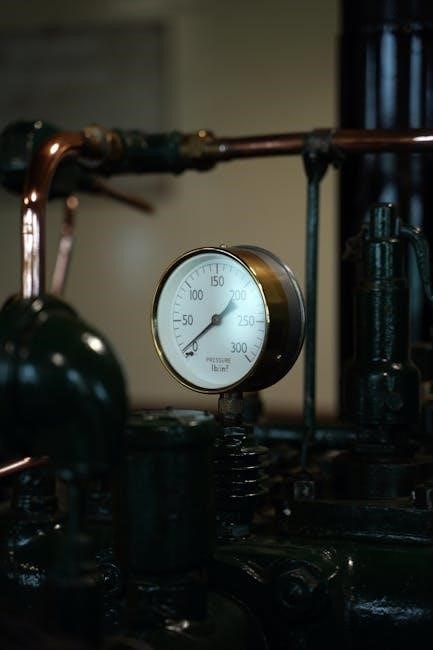
2.2 Instrumentation Symbols
Instrumentation symbols are fundamental in P&ID diagrams, representing devices like pressure transmitters, flow meters, and level indicators. These symbols are standardized to ensure universal understanding. For instance, pressure differential indicators and controllers are depicted with specific icons to denote their functions. Instruments can be categorized into field-mounted or control panel devices, with shared or dedicated controls. Standardization, as per ISA guidelines, ensures consistency, reducing interpretation errors. These symbols are detailed in PDF resources and libraries, providing clear visual representations for accurate system design and operation in various industries. They facilitate effective communication among engineers and technicians, enhancing process efficiency and safety.
2.3 Actuator Symbols
Actuator symbols in P&ID diagrams represent devices that control valve operations, such as pneumatic, hydraulic, or electric actuators. These symbols are combined with valve symbols to indicate control mechanisms. For example, solenoid actuators are shown with specific icons, while pressure safety valves use dedicated symbols. Actuator symbols are standardized to ensure clarity and consistency, aiding in the interpretation of system functionality. They are often detailed in PDF resources and libraries, providing clear visual representations for accurate system design and operation. These symbols are essential for understanding control loops and automation in process systems.

P&ID Symbols for Process Control
P&ID symbols for process control include representations of control valves, solenoid valves, and pressure safety valves. These symbols are essential for depicting automation and regulation in process systems, ensuring standardized documentation and clear communication among engineers. They are widely available in PDF resources and libraries, facilitating accurate system design and operation.
3.1 Control Valves and Their Symbols
Control valves are critical components in process systems, regulating fluid flow in response to signals. Their symbols in P&ID diagrams vary, with distinct representations for different types, such as globe, needle, and butterfly valves. These symbols often include actuator elements, indicating control mechanisms. PDF resources provide comprehensive libraries of these symbols, ensuring consistency across designs. Standardization, guided by ISA and ISO norms, enhances readability and accuracy, making these symbols indispensable for engineers in creating and interpreting process documentation efficiently. They are integral to maintaining precise system operation and safety.
3.2 Solenoid Valves and Their Representations
Solenoid valves are electromechanically operated components that control fluid flow in process systems. Their P&ID symbols combine basic valve shapes with actuator representations, indicating electrical control. Symbols 15-19, paired with actuators 13-15, denote on-off solenoid valves. These symbols are standardized in ISA S5.1 and ISO guidelines, ensuring clarity. They are widely used in automation and process control, with detailed representations available in PDF libraries. Accurate use of these symbols is crucial for interpreting system functionality and ensuring proper installation and operation in industrial settings. Their standardized forms facilitate universal understanding among engineers and technicians.
3.3 Pressure Safety Valves and Their Symbols
Pressure safety valves are critical components ensuring system protection during overpressure events. Their P&ID symbols combine a valve icon with specific actuator representations, such as symbols 2, 20, and 21, indicating their function. These symbols are standardized to meet industry regulations, ensuring clear identification and compliance. Detailed representations are available in PDF resources and libraries, aiding engineers in accurate system design. Proper use of these symbols is essential for maintaining safety and operational integrity in industrial processes, aligning with ISA and ISO standards for universal understanding and application. Their standardized forms enhance clarity in process documentation.
Software Tools for P&ID Symbol Creation
Software tools like Smap3D P&ID and CAD libraries simplify symbol creation, offering standardized templates and ISO/ISA-compliant designs. These tools enhance productivity and ensure consistency in P&ID development.
4.1 CAD Libraries for P&ID Symbols
CAD libraries provide comprehensive collections of P&ID symbols, including valves, instruments, and actuators. These libraries are designed to meet ISO and ISA standards, ensuring consistency and accuracy. Engineers can access pre-drawn shapes and templates, streamlining the design process. Libraries often include features like grid snapping for precise placement and alignment. They are compatible with various CAD software, making it easy to integrate symbols into P&ID diagrams. Regular updates ensure libraries stay current with industry standards and user needs.
4.2 ISO and ISA Standards for Symbol Design
ISO and ISA standards govern the design of P&ID symbols, ensuring global consistency and clarity. These standards define specific shapes, colors, and notations for instruments, valves, and actuators. Compliance with ISO 10628 and ISA S5.1 is crucial for accurate representation of process control systems. Standardized symbols reduce ambiguity, facilitating universal understanding among engineers. Regular updates to these standards reflect industry advancements, ensuring symbols remain relevant and effective. Adherence to these guidelines is essential for creating reliable and maintainable P&ID diagrams across industries.
Reading and Interpreting P&ID Diagrams
Reading P&ID diagrams involves understanding symbol placement, connectivity, and interpreting actuator and valve combinations to accurately visualize process control systems.
5.1 Understanding Symbol Placement and Connectivity
Understanding symbol placement and connectivity in P&ID diagrams is crucial for interpreting process control systems. Symbols are strategically positioned to reflect their physical locations and functional roles.
Connectivity is shown through lines representing pipes, electrical connections, or control signals. Standardized symbols ensure consistency, making diagrams universally understandable across industries and projects.
Actuators and valves are often combined to illustrate control logic, while instrument symbols indicate measurement or regulation points. Proper interpretation requires familiarity with ISO and ISA standards, ensuring accurate system visualization and operation.

5.2 Interpreting Actuator and Valve Combinations
Actuator and valve combinations in P&ID diagrams represent control mechanisms. Symbols for actuators, such as pneumatic or electric, are combined with valve symbols to illustrate operation modes.
These combinations indicate whether a valve is controlled manually, automatically, or through solenoid operation. For example, symbol 21 with actuator 1-16 represents a variable control valve.
Understanding these combinations is essential for interpreting system functionality, ensuring accurate process control and safe operation in industrial environments.
Best Practices for Using P&ID Symbols

Compliance with standards like ISA S5.1 ensures consistency. Document custom symbols for clarity and reuse. Regular audits maintain accuracy, preventing errors in system design and operation.
6.1 Consistency in Symbol Usage
Consistency in P&ID symbols is critical for clear communication. Using standardized symbols from ISA S5.1 ensures uniformity across designs. Custom symbols must be documented to avoid confusion. Regular training and audits help maintain consistency, preventing errors. PDF resources and CAD libraries offer pre-defined symbols, promoting adherence to standards. Consistent usage enhances readability, reduces misunderstandings, and ensures operational safety. Always reference standardized libraries to maintain uniformity in symbol application across projects.
6.2 Documenting Custom Symbols
Documenting custom P&ID symbols is essential for clarity and consistency. Companies often maintain libraries of custom symbols, combining them with standardized ones. Legend sheets in PDF format are commonly used to detail custom symbols, ensuring accessibility. Symbols 1 and 9, for example, must be documented per user standards. Proper documentation prevents errors and enhances readability. Always include custom symbols in project documentation, referencing their meanings to avoid confusion. This ensures all team members understand unique representations, aligning with industry standards like ISA S5.1.
Resources for P&ID Symbols
Free PDF downloads and online libraries offer comprehensive collections of P&ID symbols. Tools like EdrawMax and SmartDraw provide customizable templates, while ISA standards ensure compliance with industry norms.
7.1 Free PDF Downloads for P&ID Symbols
Free PDF downloads for P&ID symbols are widely available online, offering comprehensive libraries of standardized symbols. These resources include detailed diagrams for valves, instruments, and actuators, ensuring compliance with industry standards like ISA S5.1. Websites such as EdrawMax and SunCam provide downloadable PDFs with customizable templates. Users can access symbols for control valves, solenoid valves, and pressure safety valves, among others. These PDFs are invaluable for engineers, designers, and students, enabling quick reference and integration into projects. Right-clicking on desired symbols allows easy downloading for immediate use in CAD or design software.
7.2 Online Libraries and Tools
Online libraries and tools provide extensive collections of P&ID symbols, enabling efficient design and documentation. Platforms like EdrawMax and Smap3D P&ID offer customizable templates and tools for creating process diagrams. These tools support CAD integration, allowing seamless symbol placement and alignment. Many libraries include features for real-time collaboration, version control, and compliance with industry standards. Engineers and designers can access pre-built symbols for valves, instruments, and actuators, streamlining workflows. These resources are essential for ensuring accuracy and consistency in P&ID creation, catering to both professionals and learners alike.


0 Comments